هوائي
 A television antenna used for reception of television signals in VHF | |
| النوع | Passive |
|---|---|
| أول انتاج | 1898 |
| الرمز الإلكتروني | |
.svg&filetimestamp=20231103064320&) .svg&filetimestamp=20260521111049&) | |
| جزء من سلسلة مقالات عن |
| الهوائيات |
|---|
 |
الهوائي Antenna هو محول طاقة تم تصميمه ليقوم بنقل أو استقبال الموجات الكهرومغناطيسية. وبمعنى آخر فإن الهوائيات تقوم بتحويل الموجات الكهرومغناطيسية إلى تيارات الكترونية والعكس. وتستعمل الهوائيات في أنظمة مثل بث الراديو والتلفزيون ، واستكشاف الفضاء. وتعمل الهوائيات عادة في الهواء و الفضاء الخارجي ، بكلن يمكن أيضا أن يتم تشغيلها تحت الماء أو حتى تحت التربة والصخور للحصول على بعض الترداد لمسافات قصيرة.
An antenna is an array of conductor segments (elements), electrically connected to the receiver or transmitter.[1] Antennas can be designed to transmit and receive radio waves in all horizontal directions equally (omnidirectional antennas), or preferentially in a particular direction (directional, or high-gain, or "beam" antennas). An antenna may include components not connected to the transmitter, parabolic reflectors, horns, or parasitic elements, which serve to direct the radio waves into a beam or other desired radiation pattern. Strong directivity and good transmitting efficiency when transmitting are hard to achieve with antennas whose dimensions are much smaller than a half wavelength.
The first antennas were built in 1886 by German physicist Heinrich Hertz in his pioneering experiments to prove the existence of electromagnetic waves predicted by the 1867 electromagnetic theory of James Clerk Maxwell. Hertz placed dipole antennas at the focal point of parabolic reflectors for both transmitting and receiving.[2] Starting in 1895, Guglielmo Marconi began development of antennas practical for long-distance wireless telegraphy and opened a factory in Chelmsford, England, to manufacture his invention in 1898.[3]


تعريف


الهوائي جهاز يرسل ويستقبل إشارات الراديو والتلفاز والرادار. تُحْمَل تلك الإشارات بوساطة موجات كهرومغنطيسية ، وتتنقل الموجات الكهرومغنطيسية عبر الفضاء بسرعة الضوء. وهي تختلف من حيث الطول الموجي ، ذات الصلة المباشرة بترددها، أي نسبة اهتزازها. وتبث محطات الإذاعة، والتلفاز، والرادار على أطوال موجات مختلفة، لكي لا تتداخل إشاراتها بعضها ببعض. ونوعا البث بوساطة محطات الإذاعة هما تضمين الاتساع، وتضمين التردد. وعمومًا، تستخدم محطات تضمين الاتساع أطوالاً موجية تتراوح بين 10 و2000م، بينما تستخدم محطات تضمين التردد، ومحطات التلفاز أطوالاً موجية طولها 3م فأقل. أما إشارات الرادار، فإنها تستخدم أطوالاً موجية يبلغ طولها بضعة سنتمترات. [4]
أنواع الهوائيات
هوائيات الاستقبال
يعتمد حجم تعقُّد الهوائي وشكله ومداه على طول الموجة المستقبلة ومداها. كما يمكن تصميم الهوائيات بخواص اتجاهية مختلفة، بحيث لا تضطر لإرسال والتقاط الإشارات بدرجة متساوية في الاتجاهات كافة.
يتكون أبسط هوائي من سلك واحد معلَّق أفقيًا، أو من قضيب معدني مستقيم. ويوصَّل أحد جانبي الهوائي بجهاز الاستقبال. ويعمل مثل هذا الهوائي الذي يسمَّى أحياناً القطب الأحادي، على نحو أفضل عندما يتماثل طوله مع رُبع الموجة المستقبلة أو المرسلة. وتستخدم الهوائيات القضيبية مع أجهزة استقبال تضمين التردد والتلفاز النقَّالة، ومع أجهزة الإرسال والاستقبال النقالة، مثل أجهزة راديو الميدان. وتستخدم الهوائيات أحادية السلك مع العديد من مستقبلات الموجات القصيرة.
وهوائي التلفاز الأوسع استخدامًا هو ثنائي القطب، الذي يتكون من قضيب معدني مستقيم، أو من سلك منشطر في الوسط. ويتكون الهوائي الثنائي المنطوي من قطبين ثنائيين يتصلان عند الطرفين، مع كون أحدهما مشطورًا. وينبغي أن يكون مجمل طول القطب الثنائي نصف الطول الموجي المستخدم لها. كما يمكن تقوية أداء الهوائي ثنائي القطب بإضافة العاكسات، والموجِّهَات المكوَّنة من قضبان معدنية، مماثلة في الطول تقريبًا للقطب الثنائي، وموضوعة وراء القطب الثنائي وأمامه. وتُوصَّل معظم هوائيات التلفاز مع أجهزة الاستقبال بوساطة حزمة أسلاك محمية، مما يحول دون التقاط جهاز الاستقبال للتداخل من الأجهزة الكهربائية المنزلية.
تُوجد أنواع أخرى عديدة من الهوائيات. وتحوي أجهزة استقبال تضمين الإتساع الحديثة هوائيًا مكونًا من مِلّف ملفوف حول قضيب مصنوع من الفرّيت. والفرِّيت مادة مغنطيسية تقوِّي الإشارات في الملف.
هوائيات الإرسال
تماثل في التصميم هوائيات الاستقبال. ويستخدم العديد من أنظمة الاتصال والرادار الهوائي نفسه للإرسال والاستقبال؛ إلاَّ أن تصميم هوائيات الإرسال، يجب أن يكون أكثر دقة وضبطًا. فالهوائي خاطئ البعد، سيرسل مجرد جزء صغير من الطاقة المنتجة من جهاز الإرسال، كما أن موقع هوائيات الإرسال من الأهمية بمكان، إذ يجب أن توضع هوائيات تضمين التردد والتلفاز في أعلى موضع ممكن، لزيادة مداها. وسبب ذلك هو أن إشارات تضمين التردد والتلفاز تنتشر أفقيًا، ولا يمكن استقبالها وراء الأفق كما هو مُشَاهَد من هوائي الإرسال. أما إشارات تضمين الإتساع فإنها ترتد من الغلاف الجوي العلوي، ويمكنها الوصول إلى ما وراء تقوُّس الكرة الأرضية.
هوائيات الأطباق
تتخذ شكل الطبق. كما أن الطبق جزء من قطع مكافئ، والهوائي الحقيقي موضوع في بؤرته. وفي إمكان هوائي الطبق إرسال موجات الراديو في حزمة موجية ضيِّقة، أو استقبال الموجات من اتجاه محدّد للغاية. ولذلك، فإن هوائيات الأطباق تستخدم في أنظمة الرادار، ولإرسال الإشارات إلى مسافات طويلة بين المحطات الأرضية وسفن الفضاء، على سبيل المثال. كما أن أضخم هوائيات الأطباق هي الخاصة بالتلسكوبات الراديوية. ويوجد أكبرها، الذي يبلغ قُطْره 305 م، في أريسيبو، بورتوريكو. ويتزايد حاليًا إحلال الروابط الراديوية التي تستخدم هوائيات الأطباق محل خطوط الهاتف بعيدة المدى. وتوضع هذه الهوائيات في أبراج خاصة، أو فوق المباني العالية بالمدن الكبيرة.
السمات
The antenna's power gain (or simply "gain") also takes into account the antenna's efficiency, and is often the primary figure of merit. Antennas are characterized by a number of performance measures which a user would be concerned with in selecting or designing an antenna for a particular application. A plot of the directional characteristics in the space surrounding the antenna is its radiation pattern.[5]
Bandwidth
The frequency range or bandwidth over which an antenna functions well can be very wide (as in a log-periodic antenna) or narrow (as in a small loop antenna);[6] outside this range the antenna impedance becomes a poor match to the transmission line and transmitter (or receiver). Use of the antenna well away from its design frequency affects its radiation pattern, reducing its directive gain.
Generally an antenna will not have a feed-point impedance that matches that of a transmission line; a matching network between antenna terminals and the transmission line will improve power transfer to the antenna. A non-adjustable matching network will most likely place further limits the usable bandwidth of the antenna system. It may be desirable to use tubular elements, instead of thin wires, to make an antenna; these will allow a greater bandwidth. Or, several thin wires can be grouped in a cage to simulate a thicker element. This widens the bandwidth of the resonance.
Amateur radio antennas that operate at several frequency bands which are widely separated from each other may connect elements resonant at those different frequencies in parallel. Most of the transmitter's power will flow into the resonant element while the others present a high impedance. Another solution uses traps,[7] parallel resonant circuits which are strategically placed in breaks created in long antenna elements. When used at the trap's particular resonant frequency the trap presents a very high impedance (parallel resonance) effectively truncating the element at the location of the trap; if positioned correctly, the truncated element makes a proper resonant antenna at the trap frequency. At substantially higher or lower frequencies the trap allows the full length of the broken element to be employed, but with a resonant frequency shifted by the net reactance added by the trap.
The bandwidth characteristics of a resonant antenna element can be characterized according to its Q where the resistance involved is the radiation resistance, which represents the emission of energy from the resonant antenna to free space. The Q of a narrow band antenna can be as high as 15. On the other hand, the reactance at the same off-resonant frequency of one using thick elements is much less, consequently resulting in a Q as low as 5. These two antennas may perform equivalently at the resonant frequency, but the second antenna will perform over a bandwidth 3 times as wide as the antenna consisting of a thin conductor.[8]
Antennas for use over much broader frequency ranges are achieved using further techniques. Adjustment of a matching network can, in principle, allow for any antenna to be matched at any frequency. Thus the small loop antenna built into most AM broadcast (medium wave) receivers has a very narrow bandwidth, but is tuned using a parallel capacitance which is adjusted according to the receiver tuning. On the other hand, log-periodic antennas are not resonant at any single frequency but can (in principle) be built to attain similar characteristics (including feedpoint impedance) over any frequency range. These are therefore commonly used (in the form of directional log-periodic dipole arrays) as television antennas.
الكسب
الكسب هو متغير يقيس درجة directivity of the antenna's radiation pattern.[9] A high-gain antenna will radiate most of its power in a particular direction, while a low-gain antenna will radiate over a wide angle. The antenna gain, or power gain of an antenna is defined as the ratio of the intensity (power per unit surface area) radiated by the antenna in the direction of its maximum output, at an arbitrary distance, divided by the intensity radiated at the same distance by a hypothetical isotropic antenna which radiates equal power in all directions. This dimensionless ratio is usually expressed logarithmically in decibels, these units are called decibels-isotropic (dBi)
A second unit used to measure gain is the ratio of the power radiated by the antenna to the power radiated by a half-wave dipole antenna ; these units are called decibels-dipole (dBd)
Since the gain of a half-wave dipole is 2.15 dBi and the logarithm of a product is additive, the gain in dBi is just 2.15 decibels greater than the gain in dBd
High-gain antennas have the advantage of longer range and better signal quality, but must be aimed carefully at the other antenna. An example of a high-gain antenna is a parabolic dish such as a satellite television antenna. Low-gain antennas have shorter range, but the orientation of the antenna is relatively unimportant. An example of a low-gain antenna is the whip antenna found on portable radios and cordless phones. Antenna gain should not be confused with amplifier gain, a separate parameter measuring the increase in signal power due to an amplifying device placed at the front-end of the system, such as a low-noise amplifier.
Effective area or aperture
The effective area or effective aperture of a receiving antenna expresses the portion of the power of a passing electromagnetic wave which the antenna delivers to its terminals, expressed in terms of an equivalent area.[10] For instance, if a radio wave passing a given location has a flux of 1 pW / m2 (10−12 Watts per square meter) and an antenna has an effective area of 12 m2, then the antenna would deliver 12 pW of RF power to the receiver (30 microvolts RMS at 75 ohms). Since the receiving antenna is not equally sensitive to signals received from all directions, the effective area is a function of the direction to the source.
Due to reciprocity (discussed above) the gain of an antenna used for transmitting must be proportional to its effective area when used for receiving. Consider an antenna with no loss, that is, one whose electrical efficiency is 100%. It can be shown that its effective area averaged over all directions must be equal to λ2/4π, the wavelength squared divided by 4π. Gain is defined such that the average gain over all directions for an antenna with 100% electrical efficiency is equal to 1. Therefore, the effective area Aeff in terms of the gain G in a given direction is given by:
For an antenna with an efficiency of less than 100%, both the effective area and gain are reduced by that same amount. Therefore, the above relationship between gain and effective area still holds. These are thus two different ways of expressing the same quantity. Aeff is especially convenient when computing the power that would be received by an antenna of a specified gain, as illustrated by the above example.
نمط الاشعاع

The radiation pattern of an antenna is a plot of the relative field strength of the radio waves emitted by the antenna at different angles in the far field.[11] It is typically represented by a three-dimensional graph, or polar plots of the horizontal and vertical cross sections. The pattern of an ideal isotropic antenna, which radiates equally in all directions, would look like a sphere. Many nondirectional antennas, such as monopoles and dipoles, emit equal power in all horizontal directions, with the power dropping off at higher and lower angles; this is called an omnidirectional pattern and when plotted looks like a torus or donut.
The radiation of many antennas shows a pattern of maxima or "lobes" at various angles, separated by "nulls", angles where the radiation falls to zero. This is because the radio waves emitted by different parts of the antenna typically interfere, causing maxima at angles where the radio waves arrive at distant points in phase, and zero radiation at other angles where the radio waves arrive out of phase. In a directional antenna designed to project radio waves in a particular direction, the lobe in that direction is designed larger than the others and is called the "main lobe". The other lobes usually represent unwanted radiation and are called "sidelobes". The axis through the main lobe is called the "principal axis" or "boresight axis".
The polar radiation patterns of Yagi antennas become narrower, and their directivity (and thus gain) increases, when they are designed for a relatively narrow frequency range, as compared with wideband designs.[12][13]
Field regions
The space surrounding an antenna can be divided into three concentric regions: The reactive near-field (also called the inductive near-field), the radiating near-field (Fresnel region) and the far-field (Fraunhofer) regions. These regions are useful to identify the field structure in each, although the transitions between them are gradual; there are no clear boundaries.[14]
الكفاءة
Efficiency of a transmitting antenna is the ratio of power actually radiated (in all directions) to the power absorbed by the antenna terminals.[15] The power supplied to the antenna terminals which is not radiated is converted into heat. This is usually through loss resistance in the antenna's conductors, or loss between the reflector and feed horn of a parabolic antenna.
الاستقطاب
The orientation and physical structure of an antenna determine the polarization[16] of the electric field of the radio wave transmitted by it. For instance, an antenna composed of a linear conductor (such as a dipole or whip antenna) oriented vertically will result in vertical polarization; if turned on its side the same antenna's polarization will be horizontal.
In the most general case, polarization is elliptical, meaning that over each cycle the electric field vector traces out an ellipse. Two special cases are linear polarization (the ellipse collapses into a line) as discussed above, and circular polarization (in which the two axes of the ellipse are equal). In linear polarization the electric field of the radio wave oscillates along one direction. In circular polarization, the electric field of the radio wave rotates around the axis of propagation. Circular or elliptically polarized radio waves are designated as right-handed or left-handed using the "thumb in the direction of the propagation" rule.[17] Note that for circular polarization, optical researchers use the opposite right-hand rule from the one used by radio engineers.[18]
It is best for the receiving antenna to match the polarization of the transmitted wave for optimum reception. Otherwise there will be a loss of signal strength: when a linearly polarized antenna receives linearly polarized radiation at a relative angle of θ, then there will be a power loss of cos2θ .[1][19] A circularly polarized antenna can be used to equally well match vertical or horizontal linear polarizations, suffering a 3 dB signal reduction. However it will be blind to a circularly polarized signal of the opposite orientation.
Impedance matching
Maximum power transfer requires matching the impedance of an antenna system (as seen looking into the transmission line) to the complex conjugate of the impedance of the receiver or transmitter. In the case of a transmitter, however, the desired matching impedance might not exactly correspond to the dynamic output impedance of the transmitter as analyzed as a source impedance but rather the design value (typically 50 Ohms) required for efficient and safe operation of the transmitting circuitry. The intended impedance is normally resistive, but a transmitter (and some receivers) may have limited additional adjustments to cancel a certain amount of reactance, in order to "tweak" the match.
When a transmission line is used in between the antenna and the transmitter (or receiver) one generally would like an antenna system whose impedance is resistive and nearly the same as the characteristic impedance of that transmission line, in addition to matching the impedance that the transmitter (or receiver) expects. The match is sought to minimize the amplitude of standing waves (measured via the standing wave ratio; SWR) that a mismatch raises on the line, and the increase in transmission line losses it entails.
Antenna tuning at the antenna
Antenna tuning, in the strict sense of modifying the antenna itself, generally refers only to cancellation of any reactance seen at the antenna terminals, leaving only a resistive impedance which might or might not be exactly the desired impedance (that of the available transmission line).
Although an antenna may be designed to have a purely resistive feedpoint impedance (such as a dipole 97% of a half wavelength long) at just one frequency, this will very likely not be exactly true at other frequencies that the antenna is eventually used for. In most cases, in principle the physical length of the antenna can be "trimmed" to obtain a pure resistance, although this is rarely convenient. On the other hand, the addition of a contrary inductance or capacitance can be used to cancel a residual capacitive or inductive reactance, respectively, and may be more convenient than lowering and trimming or extending the antenna, then hoisting it back.
Antenna reactance may be removed using lumped elements, such as capacitors or inductors in the main path of current traversing the antenna, often near the feedpoint, or by incorporating capacitive or inductive structures into the conducting body of the antenna to cancel the feedpoint reactance – such as open-ended "spoke" radial wires, or looped parallel wires – hence genuinely tune the antenna to resonance. In addition to those reactance-neutralizing add-ons, antennas of any kind may include a transformer and / or transformer balun at their feedpoint, to change the resistive part of the impedance to more nearly match the feedline's characteristic impedance.
Line matching at the radio
Antenna tuning in the loose sense, performed by an impedance matching device (somewhat inappropriately named an "antenna tuner", or the older, more appropriate term transmatch) goes beyond merely removing reactance and includes transforming the remaining resistance to match the feedline and radio.
An additional problem is matching the remaining resistive impedance to the characteristic impedance of the transmission line: A general impedance matching network (an "antenna tuner" or ATU) will have at least two adjustable elements to correct both components of impedance. Any matching network will have both power losses and power restrictions when used for transmitting.
Commercial antennas are generally designed to approximately match standard 50 Ohm coaxial cables, at standard frequencies; the design expectation is that a matching network will be merely used to 'tweak' any residual mismatch.
Extreme examples of loaded small antennas
In some cases matching is done in a more extreme manner, not simply to cancel a small amount of residual reactance, but to resonate an antenna whose resonance frequency is quite different from the intended frequency of operation.
- Short vertical "whip"
- For instance, for practical reasons a "whip antenna" can be made significantly shorter than a quarter-wavelength and then resonated, using a so-called loading coil.
- The physically large inductor at the base of the antenna has an inductive reactance which is the opposite of the capacitative reactance that the short vertical antenna has at the desired operating frequency. The result is a pure resistance seen at feedpoint of the loading coil; although, without further measures, the resistance will be somewhat lower than would be desired to match commercial coax.[20][21]
- Small "magnetic" loop
- Another extreme case of impedance matching occurs when using a small loop antenna (usually, but not always, for receiving) at a relatively low frequency, where it appears almost as a pure inductor. When such an inductor is resonated via a capacitor attached in parallel across its feedpoint, the capacitor not only cancels the reactance but also greatly magnifies the very small radiation resistance of a small loop to produce a better-matched feedpoint resistance.[22][23]
- This is the type of antenna used in most portable AM broadcast receivers (other than car radios): The standard AM antenna is a loop of wire wound around a ferrite rod (a "loopstick antenna"). The loop is resonated by a coupled tuning capacitor, which is configured to match the receiver's tuning, in order to keep the antenna resonant at the chosen receive frequency over the AM broadcast band.
تأثير الأرض
Ground reflections is one of the common types of multipath.[24][25][26]
The radiation pattern and even the driving point impedance of an antenna can be influenced by the dielectric constant and especially conductivity of nearby objects. For a terrestrial antenna, the ground is usually one such object of importance. The antenna's height above the ground, as well as the electrical properties (permittivity and conductivity) of the ground, can then be important. Also, in the particular case of a monopole antenna, the ground (or an artificial ground plane) serves as the return connection for the antenna current thus having an additional effect, particularly on the impedance seen by the feed line.
When an electromagnetic wave strikes a plane surface such as the ground, part of the wave is transmitted into the ground and part of it is reflected, according to the Fresnel coefficients. If the ground is a very good conductor then almost all of the wave is reflected (180° out of phase), whereas a ground modeled as a (lossy) dielectric can absorb a large amount of the wave's power. The power remaining in the reflected wave, and the phase shift upon reflection, strongly depend on the wave's angle of incidence and polarization. The dielectric constant and conductivity (or simply the complex dielectric constant) is dependent on the soil type and is a function of frequency.
For very low frequencies to high frequencies (< 30 MHz), the ground behaves as a lossy dielectric,[27] thus the ground is characterized both by a conductivity[28] and permittivity (dielectric constant) which can be measured for a given soil (but is influenced by fluctuating moisture levels) or can be estimated from certain maps. At lower mediumwave frequencies the ground acts mainly as a good conductor, which AM broadcast (0.5–1.7 MHz) antennas depend on.
At frequencies between 3–30 MHz, a large portion of the energy from a horizontally polarized antenna reflects off the ground, with almost total reflection at the grazing angles important for ground wave propagation. That reflected wave, with its phase reversed, can either cancel or reinforce the direct wave, depending on the antenna height in wavelengths and elevation angle (for a sky wave).
On the other hand, vertically polarized radiation is not well reflected by the ground except at grazing incidence or over very highly conducting surfaces such as sea water.[29] However the grazing angle reflection important for ground wave propagation, using vertical polarization, is in phase with the direct wave, providing a boost of up to 6 dB, as is detailed below.
At VHF and above (> 30 MHz) the ground becomes a poorer reflector. However, for shortwave frequencies, especially below ~15 MHz, it remains a good reflector especially for horizontal polarization and grazing angles of incidence. That is important as these higher frequencies usually depend on horizontal line-of-sight propagation (except for satellite communications), the ground then behaving almost as a mirror.
The net quality of a ground reflection depends on the topography of the surface. When the irregularities of the surface are much smaller than the wavelength, the dominant regime is that of specular reflection, and the receiver sees both the real antenna and an image of the antenna under the ground due to reflection. But if the ground has irregularities not small compared to the wavelength, reflections will not be coherent but shifted by random phases. With shorter wavelengths (higher frequencies), this is generally the case.
Whenever both the receiving or transmitting antenna are placed at significant heights above the ground (relative to the wavelength), waves reflected specularly by the ground will travel a longer distance than direct waves, inducing a phase shift which can sometimes be significant. When a sky wave is launched by such an antenna, that phase shift is always significant unless the antenna is very close to the ground (compared to the wavelength).

This means that a receiving antenna "sees" the image antenna with the current in the same direction if the antenna is vertical or with the current inverted if the antenna is horizontal.
For a vertical polarized emission antenna the far electric field of the electromagnetic wave produced by the direct ray plus the reflected ray is:
The sign inversion for the parallel field case just changes a cosine to a sine:
In these two equations:
- is the electrical field radiated by the antenna if there were no ground.
- is the wave number.
- is the wave length.
- is the distance between antenna and its image (twice the height of the center of the antenna).

نمذجة الهوائيات بمعادلات خطية
- In the first approximation, the current in a thin antenna is distributed
exactly as in a transmission line. — Schelkunoff & Friis (1952)[30]
The flow of current in wire antennas is identical to the solution of counter-propagating waves in a single conductor transmission line, which can be solved using the telegrapher's equations. Solutions of currents along antenna elements are more conveniently and accurately obtained by numerical methods, so transmission-line techniques have largely been abandoned for precision modelling, but they continue to be a widely used source of useful, simple approximations that describe well the impedance profiles of antennas.[31][30]
Unlike transmission lines, currents in antennas contribute power to the radiated part electromagnetic field, which can be modeled using radiation resistance.[أ]
The end of an antenna element corresponds to an unterminated (open) end of a single-conductor transmission line, resulting in a reflected wave identical to the incident wave, with its voltage in phase with the incident wave and its current in the opposite phase (thus net zero current, where there is, after all, no further conductor). The combination of the incident and reflected wave, just as in a transmission line, forms a standing wave with a current node at the conductor's end, and a voltage node one-quarter wavelength from the end (if the element is at least that long).[31][30]
In a resonant antenna, the feedpoint of the antenna is at one of those voltage nodes.[citation needed] Due to discrepancies from the simplified version of the transmission line model, the voltage one quarter wavelength from the current node is not exactly zero, but it is near a minimum, and small compared to the much larger voltage at the conductor's end. Hence, a feed point matching the antenna at that spot requires a relatively small voltage but large current (the currents from the two waves add in-phase there), thus a relatively low feedpoint impedance.
Feeding the antenna at other points involves a large voltage, thus a large impedance,[citation needed] and usually one that is primarily reactive (low power factor), which is a terrible impedance match to available transmission lines. Therefore, it is usually desired for an antenna to operate as a resonant element with each conductor having a length of one quarter wavelength (or any other odd multiples of a quarter wavelength).
For instance, a half-wave dipole has two such elements (one connected to each conductor of a balanced transmission line) about one quarter wavelength long. Depending on the conductors' diameters, a small deviation from this length is adopted in order to reach the point where the antenna current and the (small) feedpoint voltage are exactly in phase. Then the antenna presents a purely resistive impedance, and ideally one close to the characteristic impedance of an available transmission line.
Despite these useful properties, resonant antennas have the disadvantage that they achieve resonance (purely resistive feedpoint impedance) only at a fundamental frequency, and perhaps[citation needed] some of its harmonics, and the feedpoint resistance is larger at higher-order resonances. Therefore, resonant antennas can only achieve their good performance within a limited bandwidth, depending on the Q at the resonance.
الهوائيات العملية
المقاومة المتبادلة والتفاعل بين الهوائيات
The electric and magnetic fields emanating from a driven antenna element will generally affect the voltages and currents in nearby antennas, antenna elements, or other conductors. This is particularly true when the affected conductor is a resonant element (multiple of half-wavelengths in length) at about the same frequency, as is the case where the conductors are all part of the same active or passive antenna array.
Because the affected conductors are in the near-field, one can not just treat two antennas as transmitting and receiving a signal according to the Friis transmission formula for instance, but must calculate the mutual impedance matrix which takes into account both voltages and currents (interactions through both the electric and magnetic fields). Thus using the mutual impedances calculated for a specific geometry, one can solve for the radiation pattern of a Yagi–Uda antenna or the currents and voltages for each element of a phased array. Such an analysis can also describe in detail reflection of radio waves by a ground plane or by a corner reflector and their effect on the impedance (and radiation pattern) of an antenna in its vicinity.
Often such near-field interactions are undesired and pernicious. Currents in random metal objects near a transmitting antenna will often be in poor conductors, causing loss of RF power in addition to unpredictably altering the characteristics of the antenna. By careful design, it is possible to reduce the electrical interaction between nearby conductors. For instance, the 90 degree angle in between the two dipoles composing the turnstile antenna ensures no interaction between these, allowing these to be driven independently (but actually with the same signal in quadrature phases in the turnstile antenna design).

From this definition, the currents and voltages applied in a set of coupled antennas are:
حيث:
- is the voltage applied to the antenna
- is the impedance of antenna
- is the mutual impedance between antennas and
Note that, as is the case for mutual inductances,
If some of the elements are not fed (there is a short circuit instead a feeder cable), as is the case in television antennas (Yagi-Uda antennas), the corresponding are zero. Those elements are called parasitic elements. Parasitic elements are unpowered elements that either reflect or absorb and reradiate RF energy.
In some geometrical settings, the mutual impedance between antennas can be zero. This is the case for crossed dipoles used in circular polarization antennas.
أنواع الهوائيات
Antennas can be classified by operating principles or by their application. Different authorities placed antennas in narrower or broader categories. Generally these include
These antenna types and others are summarized in greater detail in the overview article, Antenna types, as well as in each of the linked articles in the list above, and in even more detail in articles which those link to.
معرض الصور
الهوايات ومصفوفات الهوائيات
-
-
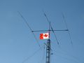
 A multi-band rotary directional antenna for amateur radio use.
 -
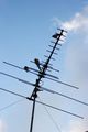 Rooftop TV antenna. It is actually three Yagi antennas. The longest elements are for the low band, while the medium and short elements are for the high and UHF band.
 -
 A terrestrial microwave radio antenna array.
 -
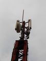
 Examples of US 136-174 MHz base station antennas.
 -
 Low cost LF time signal receiver, antenna (left) and receiver (right).
 -
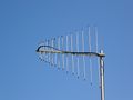 Rotatable log-periodic array for VHF and UHF.
 -
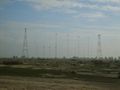 Shortwave antennas in Delano, California.


الهوائيات وبنى التدعيم
-

-
 A water tower in Palmerston, Northern Territory with radio broadcasting and communications antennas.
 -
 A three-sector telephone site in Mexico City.
 -
 Telephone site concealed as a palm tree.


رسوم بيانية كجزء من النظام
-
 Antennas may be connected through a multiplexing arrangement in some applications like this trunked two-way radio example.
 -
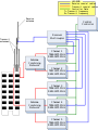
 Antenna network for an emergency medical services base station.


انظر أيضا
| هوائيات
]].- DXing
- Whip Antenna
- Radio masts and towers
- Category:Radio frequency antenna types
- Category:Radio frequency propagation
- Numerical Electromagnetics Code
- Amateur radio
- Antenna Measurements
- Cellular repeater
- Electromagnetism
- Mobile modem
- RF connector
- Radio telescope
- Satellite television
- TETRA
- واي فاي
- الهوائي الذكي
ملاحظات
- ^ أ ب Balanis, Constantine A. (2016). "Chapter 2". Antenna Theory: Analysis and Design (4th ed.). Wiley. Retrieved 2026-02-06.
- ^ Hertz, H. (1889). "[no title cited]". Annalen der Physik und Chemie. 36.
- ^ Tim Wander and Tony Crosby, The Marconi Legacy – assessing the heritage of the Wireless Communication industry in Essex, marconiheritage.org
- ^ الموسوعة المعرفية الشاملة
- ^ "Radiation Pattern". www.antenna-theory.com. Retrieved 2026-04-23.
- ^ "Antenna-Theory.com - Bandwidth". www.antenna-theory.com. Retrieved 2026-04-23.
- ^ Mark, Haverstock (2021-05-25). "Antenna Traps—A Way to Cope With Limited Space". OnAllBands (in الإنجليزية الأمريكية). Retrieved 2026-04-23.
- ^ "Q Factor and Bandwidth of a Resonant Circuit | Resonance". www.allaboutcircuits.com (in الإنجليزية). Retrieved 2026-04-23.
- ^ "Antenna Gain". www.antenna-theory.com. Retrieved 2026-04-23.
- ^ "Effective Aperture". www.antenna-theory.com. Retrieved 2026-04-23.
- ^ "Antenna Radiation Patterns: H-Plane, E-Plane, XY XZ YZ Planes". www.data-alliance.net (in الإنجليزية). Retrieved 2026-04-23.
- ^ Viezbicke, Peter P. (1976). Yagi Antenna Design. NBS Technical Note 688. Boulder, Colorado: National Bureau of Standards. Archived from the original. You must specify the date the archive was made using the
|archivedate=parameter. https://nvlpubs.nist.gov/nistpubs/Legacy/TN/nbstechnicalnote688.pdf. Retrieved on 2026-02-06. - ^ (2025) "Novel Yagi-Uda Direction Finding Antenna Backed by a Pattern Reconfigurable Microstrip Array"., USNC-URSI.
- ^ Keller, Reto B. (2023), Keller, Reto B., ed. (in en), Electromagnetic Fields, Cham: Springer International Publishing, pp. 95–109, doi:, ISBN 978-3-031-14186-7, https://doi.org/10.1007/978-3-031-14186-7_8, retrieved on 2026-04-23
- ^ "Radiated efficiency: A true measure of antenna performance". EE Times. 2010-12-07. Retrieved 2026-04-23.
- ^ "Antenna Polarization". www.data-alliance.net (in الإنجليزية). Retrieved 2026-04-23.
- ^ "Electromagnetic Plane Waves" (PDF). Ansys Innovation Courses. 2020. Retrieved 2026-02-06.
To determine handedness, point your right-hand thumb in the direction of propagation; if your fingers curl in the direction of field rotation, the wave is right-handed. If your fingers curl against the direction of field rotation, the wave is left-handed.
- ^ Ferrière, Katia; West, J. L.; Jaffe, T. R. (2021). "The correct sense of Faraday rotation" (PDF). Monthly Notices of the Royal Astronomical Society. Retrieved 2026-02-06.
Radio astronomers use the IEEE convention, according to which the electric field vector of the RCP [LCP] mode... rotates in a right-handed [left-handed] sense about k... Optical astronomers use the opposite convention.
- ^ Rumpf, Raymond C. (2017). "Topic 2 – Antenna Parameters and Figures of Merit (FOM) Continued" (PDF). empossible.net. Retrieved 2026-02-06.
The polarization loss factor is defined as PLF = … For two linearly polarized antennas rotated by an angle Ψ, PLF = cos²Ψ.
- ^ Devoldere, John (2010). "9". ON4UN's Low-Band DXing (PDF) (5th ed.). Newington, CT: ARRL. pp. 5–8. Retrieved 2026-02-06.
- ^ Ordy, Greg (2010-09-03). "Building High Power, High Q, Loading Coils". Seed Solutions. Retrieved 2026-02-06.
Let's assume that you have a resonant 1/4 wavelength vertical antenna. … If you shorten the antenna, it will develop capacitive reactance… The typical approach is to cancel the reactance with a loading coil in series at the feedpoint.
- ^ Nikolova, Natalia K. "Lecture 11: Loop Antennas" (PDF). McMaster University, ECE. Retrieved 2026-02-06.
Electrically small loops of single turn have very small radiation resistance... Their radiation resistance though can be substantially improved by adding more turns. Multi-turn loops have much greater inductive reactance, which is always compensated by a capacitor. This is actually used in narrowband receivers, where the antenna itself is a very efficient filter (together with the tuning capacitor).
- ^ Carr, Jerry. "Small Loop Antennas" (PDF). DXing.com Technical Note 8. Retrieved 2026-02-06.
The output voltage can be increased significantly if the loop is tuned to resonance by a parallel capacitor... The increase in output signal voltage is approximately equal to the Q of the tuned circuit.
- ^ Fixed Broadband Wireless System Design, p. 130, في كتب گوگل
- ^ Monopole Antennas, p. 340, في كتب گوگل
- ^ Wireless and Mobile Communication, p. 37, في كتب گوگل
- ^ Silver, H. Ward; et al., eds. (2011). ARRL Antenna Book. Newington, Connecticut: American Radio Relay League. p. 3‑2. ISBN 978-0-87259-694-8.
- ^ "M3 Map of Effective Ground Conductivity in the United States (a Wall-Sized Map), for AM Broadcast Stations". fcc.gov. 11 December 2015. Archived from the original on 18 November 2015. Retrieved 6 May 2018.
- ^ Silver 2011, p. 3‑23
- ^ أ ب ت ث Schelkunoff, Sergei A.; Friis, Harald T. (July 1966) [1952]. Antennas: Theory and practice. John Wiley & Sons. LCCN 52-5083.
- ^ أ ب ت Raines, Jeremy Keith (2007). Folded Unipole Antennas: Theory and applications. Electronic Engineering (1st ed.). McGraw Hill. ISBN 978-0-07-147485-6; ISBN 0-07-147485-4
المصادر
مصادر عامة
- Antenna Theory (3rd edition), by C. Balanis, Wiley, 2005, ISBN 0-471-66782-X;
- Antenna Theory and Design (2nd edition), by W. Stutzman and G. Thiele, Wiley, 1997, ISBN 0-471-02590-9;
- Antennas (3rd edition), by J. Kraus and R. Marhefka, McGraw-Hill, 2001, ISBN 0-072-32103-2;
- Antennenbuch, by Karl Rothammel, publ. Franck'sche Verlagshandlung Stuttgart, 1991, ISBN 3-440-05853-0; other editions (in German)
- Antennas for portable Devices, Zhi Ning Chen (edited), John Wiley & Sons in March 2007
- Broadband Planar Antennas: Design and Applications, Zhi Ning Chen and M. Y. W. Chia, John Wiley & Sons in February 2006
- The ARRL Antenna Book (15th edition), ARRL, 1988, ISBN 0-87259-207-5
"هوائي عملي" مصادر
- Antenna Theory antenna-theory.com
- Patch Antenna: From Simulation to Realization EM Talk
- Why an Antenna Radiates at ARRL
- Why Antennas Radiate, Stuart G. Downs, WY6EE (PDF)
- Understanding electromagnetic fields and antenna radiation takes (almost) no math, Ron Schmitt, EDN Magazine, March 2 2000 (PDF)
النظرية والمحاكاة
- EM Talk, "Microstrip Patch Antenna", (Theory and simulation of microstrip patch antenna)
- "Online Calculations and Conversions " Formulas for simulating and optimizing Antenna specs and placement
- "Microwave Antenna Design Calculator" Provides quick estimation of antenna size required for a given gain and frequency. 3 dB and 10 dB beamwidths are also derived; the calculator additionally gives the far-field range required for a given antenna.
- Sophocles J. Orfanidis, "Electromagnetic Waves and Antennas", Rutgers University (20 PDF Chaps. Basic theory, definitions and reference)
- Hans Lohninger, "Learning by Simulations: Physics: Coupled Radiators". vias.org, 2005. (ed. Interactive simulation of two coupled antennas)
- Justin Smith "Aerials". A.T.V (Aerials and Television), 2009. (ed. Article on the (basic) theory and use of TV aerials)
- Antennas Research Group, "Virtual (Reality) Antennas". Democritus University of Thrace, 2005.
- "Support > Knowledgebase > RF Basics > Antennas / Cables > dBi vs. dBd detail". MaxStream, Inc., 2005. (ed. How to measure antenna gain)
- Yagis and Log Periodics, Astrosurf article.
- Raines, J. K., "Virtual Outer Conductor for Linear Antennas," Microwave Journal, Vol. 52, No. 1, January, 2009, pp. 76-86
- Effect of ground references
- Electronic Radio and Engineering. F.R. Terman. MacGraw-Hill
- Lectures on physics. Feynman, Leighton and Sands. Addison-Wesley
- Classical Electricity and Magnetism. W. Panofsky and M. Phillips. Addison-Wesley
براءات الاختراع و USPTO
- CLASS 343, Communication: Radio Wave Antenna
خطأ استشهاد: وسوم <ref> موجودة لمجموعة اسمها "lower-alpha"، ولكن لم يتم العثور على وسم <references group="lower-alpha"/>
- CS1 الإنجليزية الأمريكية-language sources (en-us)
- Short description is different from Wikidata
- Articles with hatnote templates targeting a nonexistent page
- Missing redirects
- Pages using multiple image with auto scaled images
- Articles with unsourced statements from February 2024
- Pages with empty portal template
- هوائيات (راديو)
- الكترونيات راديو